The new way of mounting a disk image created with dd, dd_rescue, or ddrescue has become much simpler than before, all you need now is to issue the command
losetup --partscan --find --show disk.img
then above will tell you what loop device is being used, let us assume it is /dev/loop0, right after, a quick fdisk -l should show you the partitions, in my case, i have /dev/loop0p1 and /dev/loop0p2
mount /dev/loop0p1 /mnt
now, the first partition is mounted, to reverse this, you will need to first unmount /mnt then, you can delete the loop device with
losetup -d /dev/loop0
At this stage you can mount it like any other device, in read-write mode by default, if you want to mount it in read only mode, you can use the -o switch
sudo mount -o ro /dev/loop0px /hds/loopdevice
Now, if you have DDd a partition rather than a block device (disk) and want to mount it, you can simply mount it as a loop device, and then mount the loop device (loop0) without a Px at the end
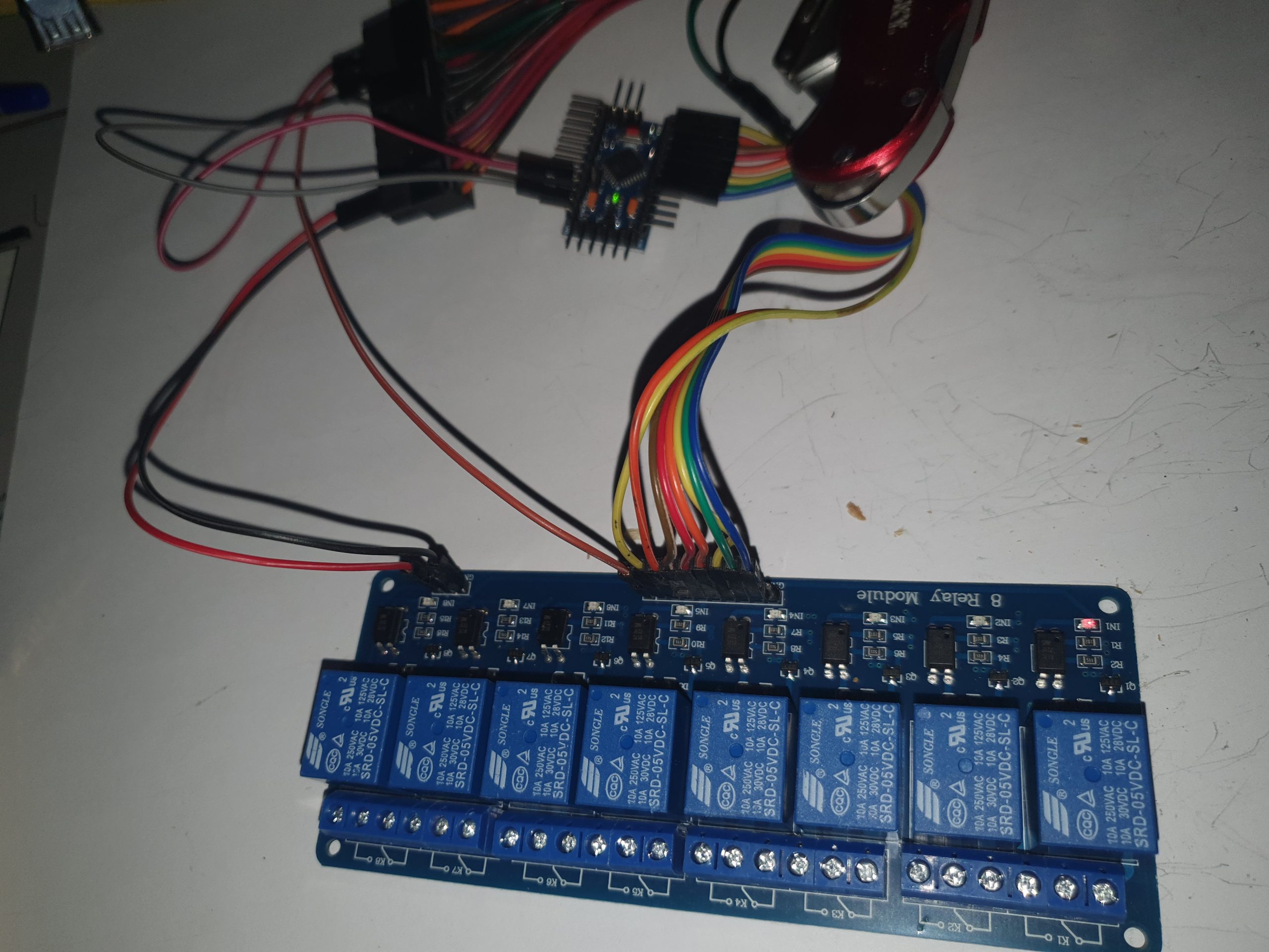
To begin with, an Arduino pro mini is capable of driving the 8 port relay with optocouplers, the power required to drive the mechanical relay is provided separately with the most common relay boards on the market, this photo (And video) should demonstrate that
In the photo above, the center connector is the COM (Common), the one to it’s left is the normally open, and the one to it’s right is normally closed
The jumper on the JD-VCC means using the same power that is powering the board for the coil, you can replace the jumper with an external power supply that doesn’t even need to have a common ground with the arduino’s power
The image above demonstrates the wiring, the power supply is a computer power supply, the relay module uses the 5V power lines from the power supply, while the Arduino uses the 3V3 line, the board’s control lines will work on logic low, hence, it will work when we are below 2V, it works perfectly fine with the 3.3V from the Arduino.
here is the source code (Very simple code, just to pull the digital lines low, then high again, the delay in the engagement is just for fun.)
// constants won't change. Used here to set a pin number:
const int ledPin =  LED_BUILTIN;// the number of the LED pin
const int relay1 = 2;
const int relay2 = 3;
const int relay3 = 4;
const int relay4 = 5;
const int relay5 = 6;
const int relay6 = 7;
const int relay7 = 8;
const int relay8 = 9;


// Variables will change:
int ledState = LOW;             // ledState used to set the LED

// Generally, you should use "unsigned long" for variables that hold time
// The value will quickly become too large for an int to store
unsigned long previousMillis = 0;        // will store last time LED was updated

// constants won't change:
const long interval = 2000;           // interval at which to blink (milliseconds)

void setup() {
  // set the digital pin as output:
  pinMode(ledPin, OUTPUT);
  pinMode(relay1, OUTPUT);
  pinMode(relay2, OUTPUT);
  pinMode(relay3, OUTPUT);
  pinMode(relay4, OUTPUT);
  pinMode(relay5, OUTPUT);
  pinMode(relay6, OUTPUT);
  pinMode(relay7, OUTPUT);
  pinMode(relay8, OUTPUT);
}

void loop() {
  // here is where you'd put code that needs to be running all the time.

  // check to see if it's time to blink the LED; that is, if the difference
  // between the current time and last time you blinked the LED is bigger than
  // the interval at which you want to blink the LED.
  unsigned long currentMillis = millis();

  if (currentMillis - previousMillis >= interval) {
    // save the last time you blinked the LED
    previousMillis = currentMillis;

    // if the LED is off turn it on and vice-versa:
    if (ledState == LOW) {
      ledState = HIGH;
      digitalWrite(ledPin, ledState);
      digitalWrite(relay1, ledState);
      delay(200);
      digitalWrite(relay2, ledState);
      delay(200);
      digitalWrite(relay3, ledState);
      delay(200);
      digitalWrite(relay4, ledState);
      delay(200);
      digitalWrite(relay5, ledState);
      delay(200);
      digitalWrite(relay6, ledState);
      delay(200);
      digitalWrite(relay7, ledState);
      delay(200);
      digitalWrite(relay8, ledState);

      delay(400);
      ledState = LOW;
      digitalWrite(ledPin, ledState);
      delay(400);
      ledState = HIGH;
      digitalWrite(ledPin, ledState);
      digitalWrite(relay2, ledState);
    } else {
      ledState = LOW;
      digitalWrite(ledPin, ledState);
      digitalWrite(relay1, ledState);
      delay(100);
      digitalWrite(relay2, ledState);
      delay(200);
      digitalWrite(relay3, ledState);
      delay(300);
      digitalWrite(relay4, ledState);
      delay(400);
      digitalWrite(relay5, ledState);
      delay(500);
      digitalWrite(relay6, ledState);
      delay(600);
      digitalWrite(relay7, ledState);
      delay(150);
      digitalWrite(relay8, ledState);
      delay(150);
      ledState = HIGH;
      digitalWrite(relay8, ledState);
      delay(700);
      ledState = LOW;
      digitalWrite(relay8, ledState);
      delay(300);
      ledState = HIGH;
      digitalWrite(relay8, ledState);
      delay(700);
      ledState = LOW;
      digitalWrite(relay8, ledState);
      delay(300);
    }

    // set the LED with the ledState of the variable:
    //digitalWrite(ledPin, ledState);
  }
}
if it is not checked on the back side, the simplest and fastest way to do this is to look at the resonator, (Clock) – usually a Crystal oscillator, but I don’t see why it can’t be a ceramic resonator, if it has something with an 8 in it, then it is probably an 8MHZ resonator, otherwise it is probably 16, where 8 comes with the 3.3V and 16 with the 5V (Scroll down to see an example)
Another way is to connect the RAW to, let’s say 12V or even 5V, and measure the voltage at the VCC pin, that would also tell you, but surely, this involves more than just looking at the board, you need to connect wires and a power supply !
mine reads 80 u (something that looks like the letter U) so it is 3v3, here is a photo
If your resonator does not read anything with an 8 on it, (My other one reads A.P), chances are it is 5 Volts
The CP2102 breakout board shown in the photo below has a selector between 3.3V and 5V.
In my case, i simply connected it the way you see it here to a USB port with 3.3V, and what do you know, it works, I have a flashing red light on the Arduino, a constant green light, and it looks like it is read to take code, the CP2102 board has a constant red light.
if you want to check that it is actually working fine, simply upload the sketch blink no delay, and then alter it a bit so that it does a double blink then wait 2 seconds, now your code is working, there you have it.
From the device manager, I can see that there is a device that looks like my adapter, namely this one
Silicon Labs CP210x USB to UART Bridge (Com3)
That thing above tells me that it has been designated the communication port number 3, which i will need in the Arduino IDE
So now i have installed and am running the Arduino IDE, selected a 3.3V Arduino board from the list and selected Com3, now i should be ready to upload a sketch, let us make a sketch that double flashes an LED every 2 seconds. here is some code to do that
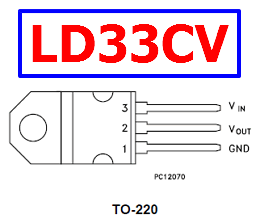
To create a tiny power supply to turn a 5V power source into 3.3V for powering the ESP8266 or ESP32, or maybe an Arduino pro mini (3.3V version), all you need to do is to couple the LD33CV-LD1117V33 with a pair of capacitors, in my case I am using the 25V/100 uf capacitor
All you need to do is the following
connect one capacitor to the pins 1 (Vin) and 3 (GND), and the other to the pins 2(Vout) and 3 (GND), and you are done.
At this stage, the ones between 1 and 3 will receive the input 5V power, While the ones closer to each other (2 and 3) will have the 3v3 output voltage that you can connect directly to your Arduino or ESP micro controller
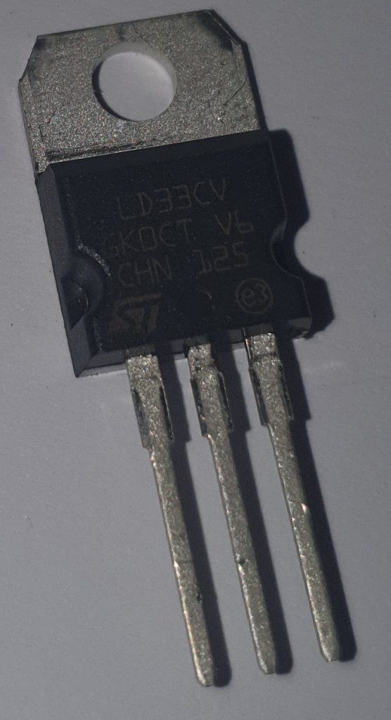
The LD1117V33 you see above (LD33CV) comes in a TO-220 package, and uses an NPN pass transistor for efficiency to provide up to 800ma of power (Cooling may be needed to achieve maximum)
Sometimes you need to find the largest sub directory in a directory, for this, the DU command has an argument that can work for you, max-depth
du -h --max-depth=1 backup-final
The above will simply list all sub directories inside the backup-final directory alongside the size of the directory (recursive, including all files in sub directories)
One of the most annoying things that can happen to you is to disconnect your laptop from the network, then realize that there was a file moving job that was running, the command is going to get disconnected before mv gets the chance to delete the source files, the new copy is a hassle, i personally use rsync to continue such a copy with the delete source files flag
But it does not have to be this way, you can move the mv command to the background, the steps are simple
First, to suspend the job, you need to hit CTRL+z , once suspended, you should see a job number in the suspend acknowledgement
CTRL+Z
Now, the next step is to disown the job, because right now, if you close your terminal window, the job will still be terminated
disown -h %1 (replace one with your own job number which may be 1)
Now to get the job running again but in the background
bg 1
That is it, you can now close (logout) your terminal window
So the summery
ctrl+z
disown -h %1
bg 1
logout
Now mind you, the output to stdout will not display (In most cases), you will need to use process status ps x to see the process.
If you want to bring back the command into the foreground, all you need to do is execute the command jobs (to find the ID), then run the command fg 1 (if it was job number one), then to hide it again, you can ctrl+z then bg 1 again (No need to disown it this time)
Sometimes, you realize you would want to use LVM in a computer but you want a tutorial to take you there fast, So i have put this post together to get you up and running in 10 minutes or less.
First, let us start with the tools, install the following packages in your debian installation, (Debian 10-Buster in this tutorial)
In this tutorial, I have two 8TB disks i want to combine with LVM to use as one
1- Create partitions of type LVM on the disks
Why not use the disk without a partition ? See this post
Start by running parted on every physical disk, and creating a big partition to span the whole disk (Or if you are using empty spaces on old disks, any partition is good enough really)
In my example, where i wish to combine /dev/sdb and /dev/sdc into one logical volume (To be used as one block)
parted /dev/sdb
mklabel gpt
unit mib
mkpart primary ext4 1 100%
set 1 lvm on
Now, repeat the above, but this time for /dev/sdc
1- Prepare the physical volumes to be added to volume groups (those two partitions) (For instructions on how to add disks directly without an underlying partition which is not recommended, see here)
pvcreate /dev/sdb1 /dev/sdc1
Now, you can see what we have with the commands
pvdisplay or pvs
2- Add the PVs to a logical volume
vgcreate LVMGroup /dev/sdb1 /dev/sdc1
   Volume group "LVMGroup" successfully created
this will create a volume group (VG) called LVMGroup, you can see the VGs you have with the commands (vgdisplay, vgscan, and vgs)
rsync is better than mv to move files because of a few reasons
First, it gives you much more control, for example the following command
rsync -a -v --ignore-existing --remove-source-files /hds/iscsi/all_new /hds/usb
Does not copy the files that are already at destination, meaning if there is a file with the same name in the same directory at the destination, it will not be overwritten, files moved will be deleted, and files that had counterparts and not moved will not be deleted
rsync -a -v --remove-source-files /hds/iscsi/all_new /hds/usb
While the command above will overwrite files, and delete whatever we have moved ! if files exist on the destination, it does not seem to be overwriting them, but it is probably somehow comparing them, then deleting the original
I had to investigate this as a move command resulting in an error did not remove the files, the error was relevant to the file name being too long
When tarring a file, even if the process (Nice) priority is low, sometimes the IO will make the computer unusable, so what you can do it ask Linux to only work on the IO intensive job when there is no other application requiring IO
ionice -c 3 -p $PID
The above class (3) means only if no other application is using this disk
We use cookies to ensure that we give you the best experience on our website. If you continue to use this site we will assume that you are happy with it.Ok